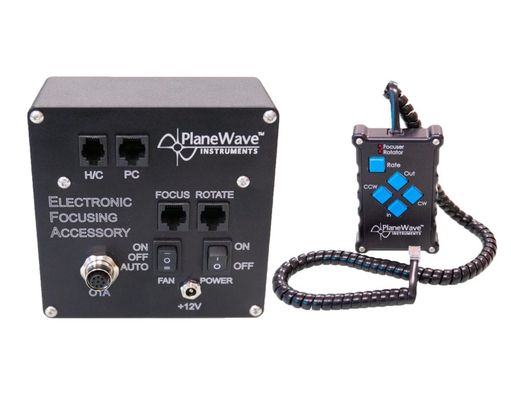
Electronic Focus Accessory (EFA) Kit
Price: $920.00 – $1,150.00
- The EFA kit automates focusing on the optional Hedrick Focuser, or IRF90 rotating focuser.
- Monitors temperature (primary mirror and OTA back-plate).
- Controls the fans built-in to CDK telescopes.
- Ensure you have the proper EFA kit selected for your telescope below.
- 125901-Kit is for CDK12.5 OTAs.
- 240901-Kit is for CDK14, CDK17, CDK20, CDK24 OTAs, and CDK700.
Description
Description
The EFA control box can be mounted to the back plate of any PlaneWave telescope OTA (12.5 through 24 inches). The EFA Kit plugs into the temperature sensors and fan control systems that are built into each telescope. A Hand Control is provided to control an optional Focuser or Rotator when standing at the eyepiece. The EFA kit comes with PlaneWave Interface (PWI3), a software package that controls all EFA functions from a PC. Cables and adapters are provided to attach the EFA kit to a PC. The EFA kit is ASCOM compatible.
Specifications
Specifications
EFA PC Port Protocol Overview
- Message Packet:
- SOM Start Of Message byte must start every message packet. SOM = 59 = 0x3B
- NUM Number of Bytes is calculated by: NUM = [(Packet Byte Count) – 3] (Note: The bytes SOM, NUM, and CHK are not counted in NUM)
- SRC Source Address
- RCV Receiver Address
- CMD Command See below for a list.
- DA1 DATA1 Optional data byte, Some commands require data.
- DA2 DATA2 Optional data byte, Some commands require data.
- DA3 DATA3 Optional data byte, Some commands require data.
- CHK Checksum The last byte of the message packet is a Checksum. It is calculated by summing the bytes of the packet, excluding the SOM and CHK, and taking the Least Significant Byte of the two’s complement. Examples are below.
- When data bytes combine to represent an integer, the MOST-SIGNIFICANT data byte is sent first.
- All messages require the Receiver to respond. If the “no data” response is necessary, the Receiver will respond by sending a message with the CMD it received. NOTE: THE EFA RESPONDS TO ANY MESSAGE RECEIVED, EVEN INVALID COMMANDS!
- Port Settings:
- Baud Rate: 19200
- Parity: None
- Data bits: 8
- Stop bits: 1
- RTS/CTS Flow Control
- PC waits for the CTS to be clear
- PC enables the RTS
- PC sends message packet
- PC clears the RTS
Focuser
- Scale Factor: (115134.42 Encoder Counts) = (1 mm Focuser Travel)
- Nominal Focuser Travel: 33 mm = 3799422 Encoder Counts
- Focuser Encoder = 0 when racked completely in
Standard Addresses
| Device | Decimal | Hex | |
| PC | Computer | 32 | 0x20 |
| HC | Hand Control | 14 | 0x0D |
| FOC | Focuser | 18 | 0x12 |
| FAN | Fan Controller | 19 | 0x13 |
| TEMP | Temperature Sensor | 18 | 0x12 |
Commands
| Command | Description | CMD (Hex) | Send Data | Response Data | Send Sample (Hex) | Respond Sample (Hex) |
| MTR_GET_POS | Get position | 0x01 | 3 bytes (encoder position) | 3B 03 20 12 01 CA | 3B 06 12 20 01 00 00 00 C7
Encoder Position = 0 |
|
| MTR_GOTO_POS2 | GOTO position | 0x17 | 3 bytes (encoder position) | 1 byte (1=OK) | Goto Position = 0x140000 = 1310720 | |
| MTR_OFFSET_CNT | Set current focuser encoder position. Often used to set focuser encoder to Zero. | 0x04 | 3 bytes (encoder position) | 1 byte (1=OK) | 3B 06 20 12 04 14 00 00 B0
Set Encoder Position = 0x140000 = 1310720 |
3B 04 12 20 04 01 C5 |
| MTR_GOTO_OVER | Determine if the motor is moving during a GOTO? | 0x13 | 1 byte (255=YES, 0=NO) | 3B 03 20 12 13 B8 | 3B 04 12 20 13 FF B8
Goto is Over |
|
| MTR_SLEWLIMITMAX | Set the Maximum Slew Limit. | 0x1B | 3 bytes | 1 byte (1=OK) | 3B 06 20 12 1B 3B 82 60 90
Set Min Slew Limit = 0x3B8260 = 3900000 |
3B 04 12 20 1B 01 AE |
| MTR_SLEWLIMITGETMAX | Returns the Maximum Slew Limit in encoder ticks | 0x1D | 3 bytes (encoder position) | 3B 03 20 12 1D AE | 3B 06 12 20 1D 3A 4F A5 7D
Maximum Slew Limit = 0x3A4FA5 = 3821477 |
|
| MTR_PMSLEW_RATE | Move the motor positive. Motor will stop when the Max Slew Limit is reached. | 0x24 | One byte for the speed (stop to fastest) = (0x00 to 0x09) | 1 byte (1=OK) | 3B 04 20 12 24 09 9D
Go Positive Top Speed |
3B 04 12 20 24 01 A5 |
| MTR_NMSLEW_RATE | Move the motor negative. Motor will stop when the Min Slew Limit is reached. | 0x25 | One byte for the speed (stop to fastest) = (0x00 to 0x09) | 1 byte (1=OK) | 3B 04 20 12 25 09 9C
Go Negative Top Speed |
3B 04 12 20 25 01 A4 |
| TEMP_GET | Get the temperature of one sensor | 0x26 | One byte address(Primary=0, Ambient=1, Secondary=2) | 3 bytes (byte1=address, [byte2 & byte3] = Temperature…See Formula Below) | 3B 04 20 12 26 01 A3
Request Temp for ambient |
3B 05 12 20 26 5C 01 46
Temp=5C01 (see below for conversion to Celcius) |
| FANS_SET | Set the fans, on or off. | 0x27 | 1 byte (1=ON, 0=OFF) | 1 byte (1=OK) | 3B 04 20 13 27 01 A1
Set FANS=ON |
3B 04 13 20 27 01 A1 |
| FANS_GET | Get the fans state, on or off. | 0x28 | 1 byte (0=ON, 3=OFF) | 3B 03 20 13 28 A2 | 3B 04 13 20 28 00 A1
FANS=ON |
|
| MTR_GET_CALIBRATION_STATE | Determine if the focuser as been calibrated. Useful for Handcontrol and PWI Focus software. | 0x30 | 1 byte (0x40) | 1 byte (0=NO, 1=YES) | 3B 04 20 12 30 40 5A | 3B 04 12 20 30 01 99
Motor = calibrated. |
| MTR_SET_CALIBRATION_STATE | Set the calibration state for the focuser. Useful for Handcontrol and PWI Focus software. | 0x31 | 2 bytes (Calibrated = 40 01) and (Not = 40 0) | 1 byte (1=OK) | 3B 05 20 12 31 40 01 57
Set calibration = true |
3B 04 12 20 31 01 98 |
| MTR_GET_STOP_DETECT | Determine if Motor will stop when the focuser hits a physical hardstop. | 0xEE | 1 byte (1=YES, 0=NO) | 3B 03 20 12 EE DD | 3B 04 12 20 EE 01 DB
Stop Detect = enabled |
|
| MTR_STOP_DETECT | Set the controller to stop when focuser hits a physical hardstop. | 0xEF | 1 byte (1=YES, 0=NO) | 3B 04 20 12 EF 01 DA
Set Stop Detect = enabled |
3B 03 12 20 EF DC | |
| MTR_GET_APPROACH_DIRECTION | Get the approach of motor during a goto | 0xFC | 1 byte (0=negative, 1=positive=default) | 3B 03 20 12 FC CF | 3B 04 12 20 FC 00 CE
Motor is set to approach from positive, this is default. |
|
| MTR_APPROACH_DIRECTION | Get the approach of motor during a goto | 0xFD | 1 byte (0=negative, 1=positive=default) | 1 byte (1=OK) | 3B 04 20 12 FD 00 CD
Set APPROACH = positive, this is default. |
3B 04 12 20 FD 01 CC |
| GET_VERSION | Get Firmware Version | 0xFE | 2 bytes (byte1=Major, second byte2=minor) | 3B 03 20 12 FE CD | 3B 05 12 20 FE 01 05 C5
Version = 1.5 |
Convert Temperature to Celsius
- The response request for temperature is 3 bytes
- byte1=address, byte2 & byte3 are used to calcuate the temperature
- If there is no sensor for the address requested, the response bytes are 0x7F7F
- (Primary=0, Ambient=1, Secondary=2)
Conversion of the two received bytes to Celsius
int rawTemp = byte2*256 + byte3
bool tempIsNeg = false
if(rawTemp > 32768)
{
tempIsNeg = true
rawTemp = 65536 – rawTemp
}
int intPart = RawTemp / 16
int fractionDigit = (RawTemp – intPart) * 625 / 1000
float celciusTemp = intPart + fractionDigit / 10
if(tempIsNeg) celciusTemp = -celciusTemp
PC Port Cable – RJ45 and DB9
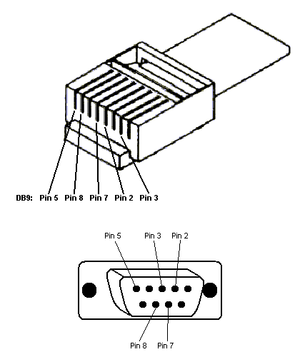
- 2 Receive Data
- 3 Transmit Data
- 5 Signal Ground
- 7 Request To Send
- 8 Clear To Send
Downloads
Downloads
PlaneWave AutoFocus COM Interface 13.56 KB 2646 downloads
PlaneWave AutoFocus COM Interface ...